Click here for INCH hole clearances
Using the correct diameter of clearance hole is important and should be considered in the design.
A small diameter clearance hole can create bolt or screw interference problems between the holes of the parts being assembled if careful tolerancing is not applied on the manufacturing drawing. A pair of holes on mating parts needs to be well enough aligned so that the bolt or screw can pass through without any interference. As the position of each hole can shift slightly in different directions due to the manufacturing tolerances, the clear area for the bolt or screw to fit through unobstructed decreases. If the clearance diameter of each hole is small, this clear gap for the bolt or screw to pass through unobstructed is also small. This risk is made even greater as the number of bolts in the array increases.
On the other hand, a clearance hole that is larger decreases the bearing surface areas under the bolt head or nut face. This results in an increase in the bearing load stresses on the surfaces of the parts and fasteners.
The larger the clearance holes, the looser the positional tolerances of those holes can be and still achieve the same clear area for the bolt or screw to pass through unobstructed. This looser positional tolerance has the benefit of making the manufacturing process cheaper and lowering the risk of parts not fitting together during assembly.
Fine
Fine clearance holes diameters are typically used when some additional location of the parts is required. Check the positional tolerancing on both parts to confirm there will always be clearance for the bolts or screws to pass unobstructed.
Medium
Medium clearance holes are a good general happy medium.
Coarse
Coarse clearance holes have 2 advantages. Firstly, the risk of a mismatch between the holes of the mating parts preventing the bolts or screws passing through unobstructed is far lower. Secondly, on thick flanges the perpendicularity of the machined clearance holes becomes a concern. As an example, if the perpendicularity of a machined hole is 1 degree away from perpendicular, then for a 2 mm thin flange the risk is negligible but if the flange is 50 mm thick, the entrance of the hole on the one side of the flange and the exit of the hole on the other side of the flange can be about 0.8 mm mismatched. Unless the clearance hole is large enough, a bolt or screw may not pass through perpendicularly.
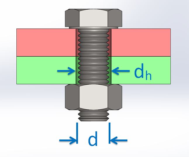
| Thread Diameter (d) | Clearance Hole Diameter (dh) | ||
| Series: | |||
| Fine | Medium | Coarse | |
| 1 | 1.1 | 1.2 | 1.3 |
| 1.2 | 1.3 | 1.4 | 1.5 |
| 1.4 | 1.5 | 1.6 | 1.8 |
| 1.6 | 1.7 | 1.8 | 2 |
| 1.8 | 2 | 2.1 | 2.2 |
| 2 | 2.2 | 2.4 | 2.6 |
| 2.5 | 2.7 | 2.9 | 3.1 |
| 3 | 3.2 | 3.4 | 3.6 |
| 3.5 | 3.7 | 3.9 | 4.2 |
| 4 | 4.3 | 4.5 | 4.8 |
| 4.5 | 4.8 | 5 | 5.3 |
| 5 | 5.3 | 5.5 | 5.8 |
| 6 | 6.4 | 6.6 | 7 |
| 7 | 7.4 | 7.6 | 8 |
| 8 | 8.4 | 9 | 10 |
| 10 | 10.5 | 11 | 12 |
| 12 | 13 | 13.5 | 14.5 |
| 14 | 15 | 15.5 | 16.5 |
| 16 | 17 | 17.5 | 18.5 |
| 18 | 19 | 20 | 21 |
| 20 | 21 | 22 | 24 |
| 22 | 23 | 24 | 26 |
| 24 | 25 | 26 | 28 |
| 27 | 28 | 30 | 32 |
| 30 | 31 | 33 | 35 |
| 33 | 34 | 36 | 38 |
| 36 | 37 | 39 | 42 |
| 39 | 40 | 42 | 45 |
| 42 | 43 | 45 | 48 |
| 45 | 46 | 48 | 52 |
| 48 | 50 | 52 | 56 |
| 52 | 54 | 56 | 62 |
| 56 | 58 | 62 | 66 |
| 60 | 62 | 66 | 70 |
| 64 | 66 | 70 | 74 |
| 68 | 70 | 74 | 78 |
| 72 | 74 | 78 | 82 |
| 76 | 78 | 82 | 86 |
| 80 | 82 | 86 | 91 |
| 85 | 87 | 91 | 96 |
| 90 | 93 | 96 | 101 |
| 95 | 98 | 101 | 107 |
| 100 | 104 | 107 | 112 |
| 105 | 109 | 112 | 117 |
| 110 | 114 | 117 | 122 |
| 115 | 119 | 122 | 127 |
| 120 | 124 | 127 | 132 |
| 125 | 129 | 132 | 137 |
| 130 | 134 | 137 | 144 |
| 140 | 144 | 147 | 155 |
| 150 | 155 | 158 | 165 |
Reference: ISO 273-1979
Disclaimer: The information on this page is provided in good faith. Ezee Calc assumes no responsibility or liability for any errors or omissions in the content of this site. Information contained in this site is provided on an “as is” basis with no guarantee of completeness, accuracy or usefulness.