
Status: Under development
Last updated: 16 July 2026
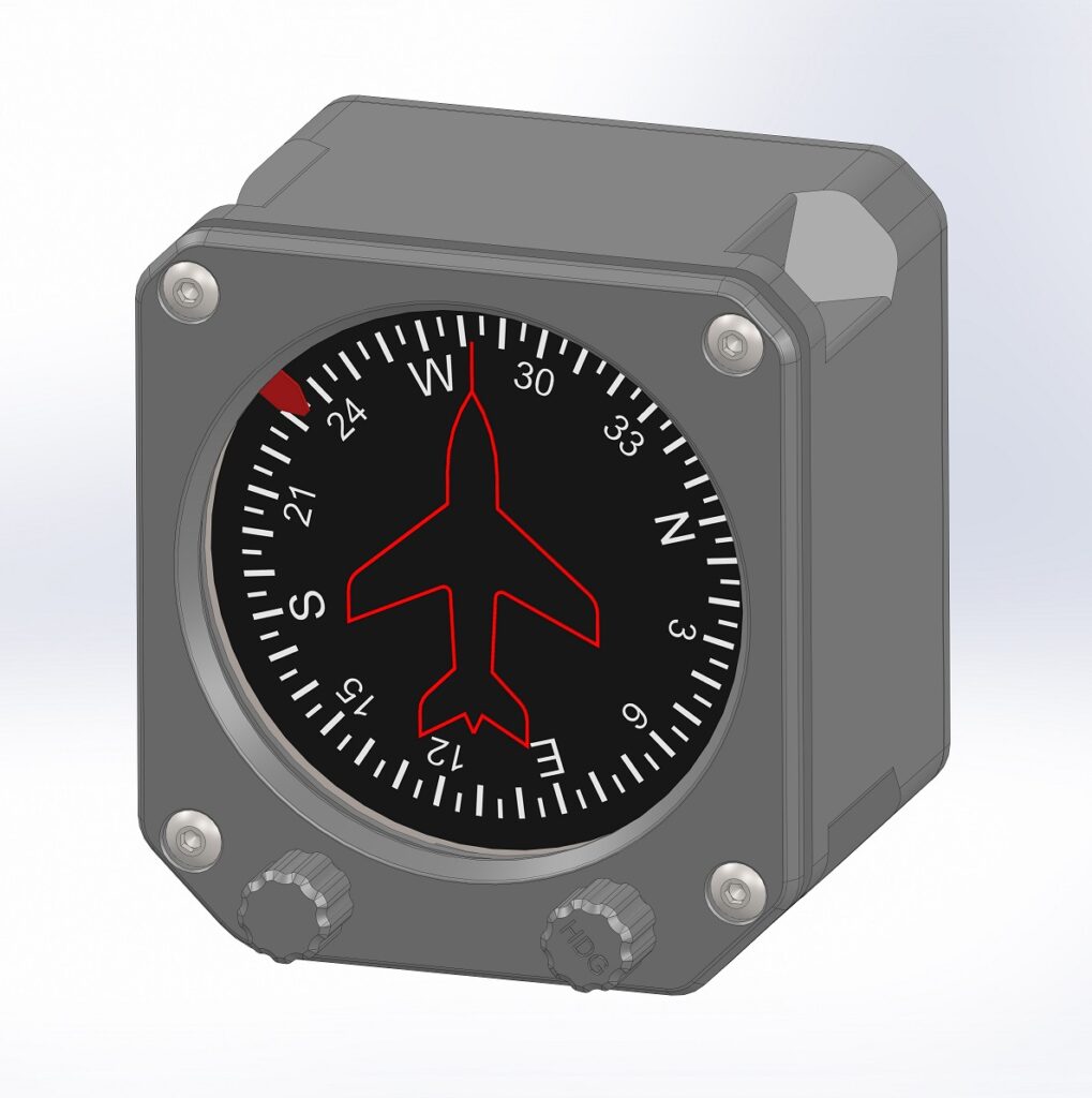
The flight simulator heading indicator is the instrument we designed first because it is one of the most complex. By perfecting its challenging mechanism first, which also requires two rotary encoders and a heading bug, we establish a robust component baseline. Simpler instruments (e.g., the airspeed indicator or altimeter) will then be developed as stripped-back versions to maximize part reuse.
Inside the housing, two 28BYJ-48 stepper motors independently drive the main dial and the heading bug. Each motor pairs with an infrared transmitter and receiver to home the shafts to a known reference position upon startup.
A dedicated PCB mounts the two rotary encoders. For instruments requiring only a single encoder, such as the altimeter, the exact same PCB is utilized but assembled with only one encoder populated.
The main PCB mounts to the back cover, utilizing an RJ45 connector for external data and power interfaces. Powered by an Arduino Nano, this universal PCB serves all instruments and includes headers for two stepper motors, two servo motors, two infrared beam breaks, two rotary encoders, and backlighting. Because the Arduino Nano has limited GPIO pins, some functions share pins, meaning not all interfaces can operate simultaneously.
What still needs to be done?
- Route the main PCB – Currently in progress.
- Route the rotary encoder PCB.
- Design cable restraint clips for the infrared transmitter / receiver wiring looms.
- Write the Arduino code.